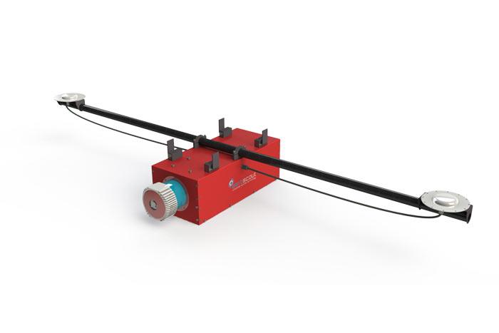
In the recent years, Aeroscout gained deeply knowledge of integrating high precision industrial sensors for survey and scientific applications on UAV helicopters. As a logical consequence, Aeroscout integrated the AisaKESTREL 10 hyperspectral imaging camera developed by Specim.
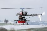
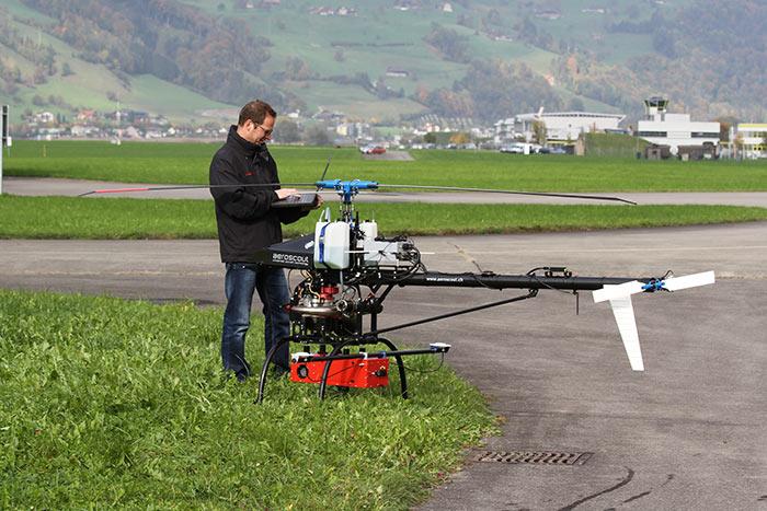
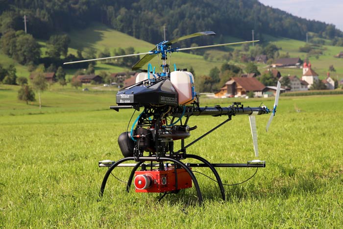
The AisaKESTREL 10 is especially designed for UAVs, but makes no compromises in data quality compared to heavier sensors which are traditionally used on manned aircrafts. With its 5kg, the AisaKESTREL 10 fits perfectly on the Scout B1-100 UAV helicopter which can carry a maximum of 18kg. It leaves enough free payload capacity to integrate a high-grade dual-GPS antenna INS/GPS navigation system as well as a broadband datalink, batteries and an advanced vibration damping system. This combination of components and UAV leads to great usability paired with an outstanding data quality.
During the mission flight, the onboard scanning process can be monitored by the well-proven ALMI software (airborne laser scanning) on the ground control laptop. The ALMI software was adapted to the special requirements of hyperspectral imaging.
aisaKESTREL 10 Facts
| Spectral range | 400 - 1000nm |
| F/# | F/2.4 |
| Smile/Keystone | <0.5pixel |
| Signal-to-noise ratio (peak) | 400 - 800 |
| Spatial resolution | 1312 or 2048pixel |
| Field of view | 40° |
Typical Scenario
| Area covered [km2] | 1 |
| Points density [pts/m2] | 200 |
| Mission duration [min] | 60 |
| Flight velocity [m/s] | 6 |
| Flight altitude [m AGL] | 100 |
| Scanning angle (fix) [deg] | 40 |
| Spatial resolution[-] | 2048 |
| Frame rate [Hz] | 50 |
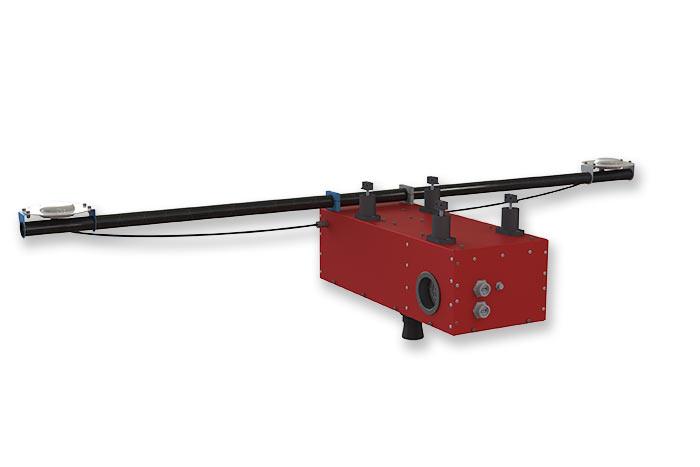
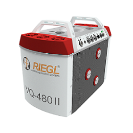
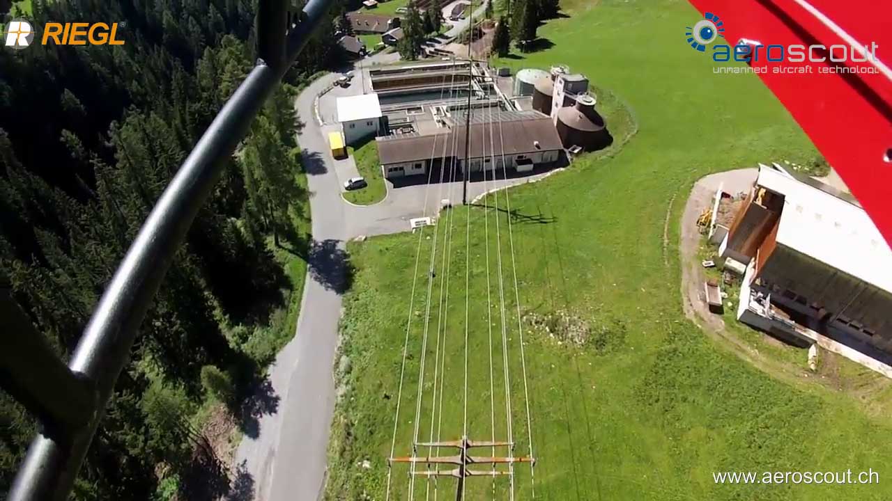
The Scout B-330 UAV helicopter can be equipped with the Riegl VQ-480-II laser scanner which provides high speed data acquisition using a narrow infrared laser beam and a fast line scanning mechanism. High-accuracy laser ranging is based on Riegls's unique echo digitization and online waveform processing, which allows achieving superior measurement results even under adverse atmospheric conditions, and the evaluation of multiple target echoes. The narrow scan angle and the maximum measurement range was designed to fly in higher altitude compared to the VUX-1UAV laser scanner.
Technical Data
| high accuracy ranging based on RIEGL Waveform-LiDAR technology | |
| high laser pulse repetition rate up to 2 MHz | |
| measurement rate up to 1,250,000 measurements/sec | |
| perfectly linear and parallel scan lines | |
| compact, & lightweight design: ready for integration in UAVs with higher payload capacity | |
| wide field of view of 75° | |
| mechanical and electrical interface for IMU/GNSS integration | |
| removeable storage card and integrated Solid State Disk (SSD) for data storage | |
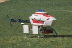
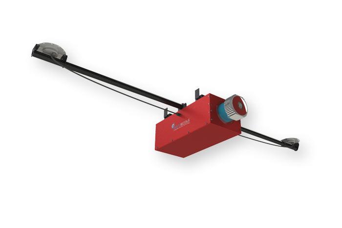
The Aeroscout UAV helicopters can be equipped with the Riegl VUX-1UAV which is a lightweight and compact laser scanner, meeting the challenges of emerging survey solutions by UAVs, both in measurement performance as in system integration. The VUX-1 provides high speed data acquisition using a narrow infrared laser beam and a fast line scanning mechanism. The enclosure and the payload mounting system is designed by Aeroscout. The very effective vibration dampers were proved to push the accuracy of the laser scanner and the GPS/INS close to laboratory test conditions which is hardly achieved by other system.
| Maximum measurement range | up to 920m |
| Max. Operating Flight Altitude AGL | 350 m |
| Max. Operating Flight Altitude AGL at 550 kHz | 110 m |
| Minimum range | 5 m |
| Accuracy | 25 mm |
| Precision | 25 mm |
| Effective measurement rate | 500000 meas/sec |
| Laser wavelength | near infrared |
| Beam divergence | 0.5 mrad |
| Scan angle range | 330° |
| Scanning mechanism | rotating polygon mirror |
| Scan speed | 200 scans/sec |
| Angle measurement resolution | 0.006° |
| Measurements per line | 200 scans/sec |
ALMI Technology - Airborne Laser Scanning and Monitoring Integration
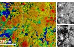
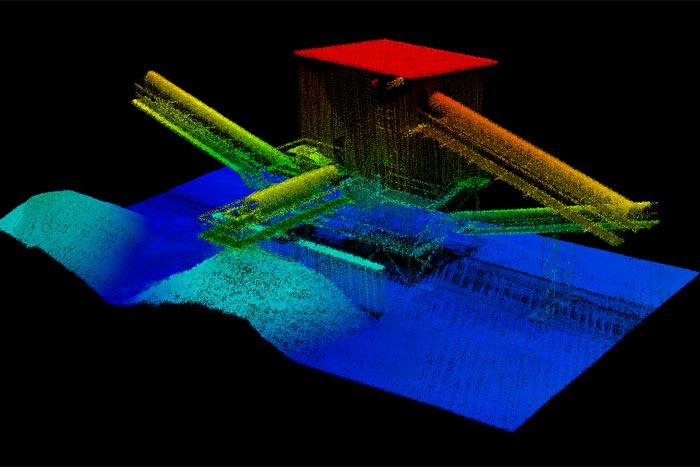
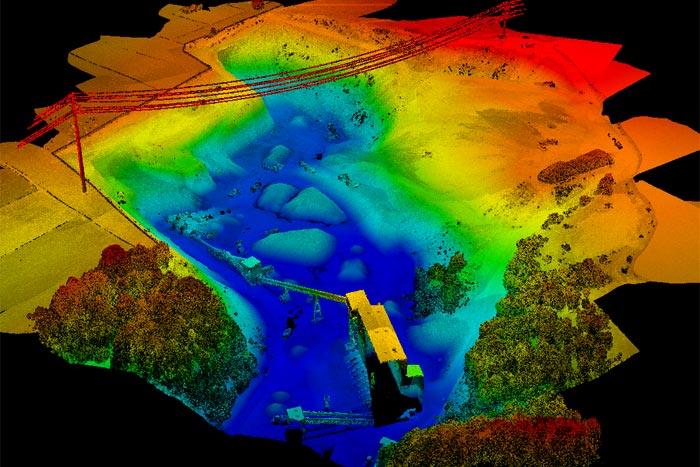
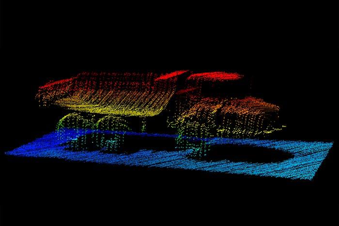
The ALMI technology has been developed by Aeroscout GmbH for professional 3D airborne laser scanning (lidar) based on an unmanned aerial vehicle (UAV). It allows continuously monitored, accuracy controlled, vibration-isolated, and time-synchronized airborne laser scanning from the UAV system. The quality of the laser scans performed with ALMI were proved several times in different case studies (latest here). Aeroscout knows that most likely, the data quality cannot be achieved with competitor equipment.
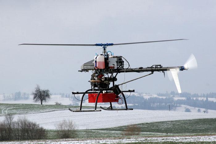
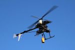
The ALMI technology has been developed, tested, and successfully demonstrated on the Aeroscout Scout B1-100 UAV helicopter. However, the ALMI technology can also be applied on other UAV systems.
The UAV payload section includes the laser scanner tightly coupled with a high-grade dual-GPS antenna INS/GPS navigation system as well as an GPS reference station.
Aeroscout started developing the ALMI technology as a contributor of the EU research project “BACS” at ETH Zurich (2006-2010). In the last years, the knowledge was transferred into hard- and software for the industrial requirements of airborne laser scanning.
The ALMI technology will allow to perform successful airborne lidar based on the Scout B1-100 UAV helicopter.
Facts of the ALMI Technology
The ground control station can remotely communicate with all payload components to configure them before the flight.
The scanner can be started and stopped remotely from the ground control station (GCS) during the mission flight.
Status information of the laser scanner and the INS/GPS is sent to the ground control station to monitor the ongoing data acquisition during the flight.
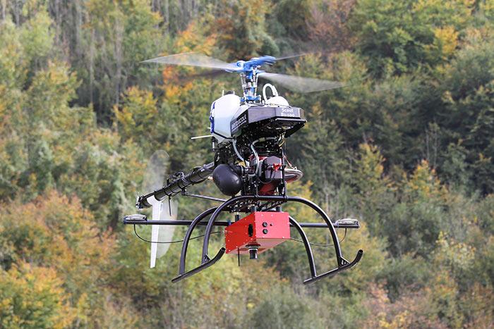
The hardware integration of the payload includes an advanced vibration damping to protect the sensitive parts from vibration caused by the engine and the rotors of the UAV system.
The ALMI technology offers various kind of data interfaces such as Ethernet, USB, RS232, RS485, etc. The remote download of recorded 3D laser data and navigation data allows immediate performance control and feedback on the field.
Features of the ALMI Technology
The ALMI technology
- ... can be combined with all state-of-the-art RIEGL laser scanner.
- ... has been optimized for the OXTS INS/GPS navigation unit
- ... allows to integrate a differential GPS reference station providing differential corrections.
- ... can be upgraded to store the differential GPS correction data on ground.
- ... provides online status information of the scanner and the INS/GPS system.
- ... provides online feedback for the recorded data
- ... allows remote access on the recorded data
- ... can be upgraded with a digital photo camera for point cloud photo overlay.
Typical Scenario
The typical scenario of a mission flight depends on the application. The following table shows three different scenarios of different size. The endurance of the Scout B1-100 UAV helicopter is 90 minutes. The scan flight is 60 minutes which allows enough safety margin for starting, flying to the starting point, return, and landing the UAV. A point density of up to 300 points per square meter (28 points per square foot) is an excellent value compared to manned airborne laser scanning with a traditional airplane which typically has 3-5 points per square meter.
| Area covered [km2] | 1 | 6 | 10 |
| Flight velocity [m/s] | 5 | 10 | 15 |
| Flight altitude [m AGL] | 50 | 80 | 100 |
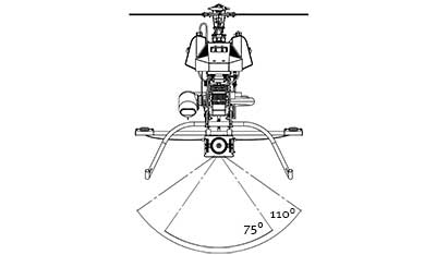
| Scanning angle [deg] | 75 | 110 | 110 |
| Point to point distance [cm] | 6 | 10 | 15 |
| Line to line distance [cm] | 6 | 10 | 15 |
| Points density [pts/m2] | 300 | 100 | 50 |
| Mission duration [min] | 60 | 60 | 60 |
| Data size [GB] | 8 | 12 | 12 |
| Photo overlay: | yes | no | no |
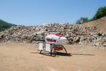
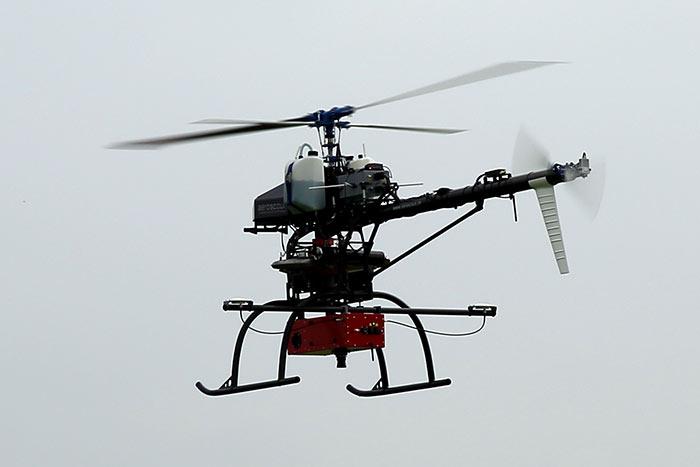
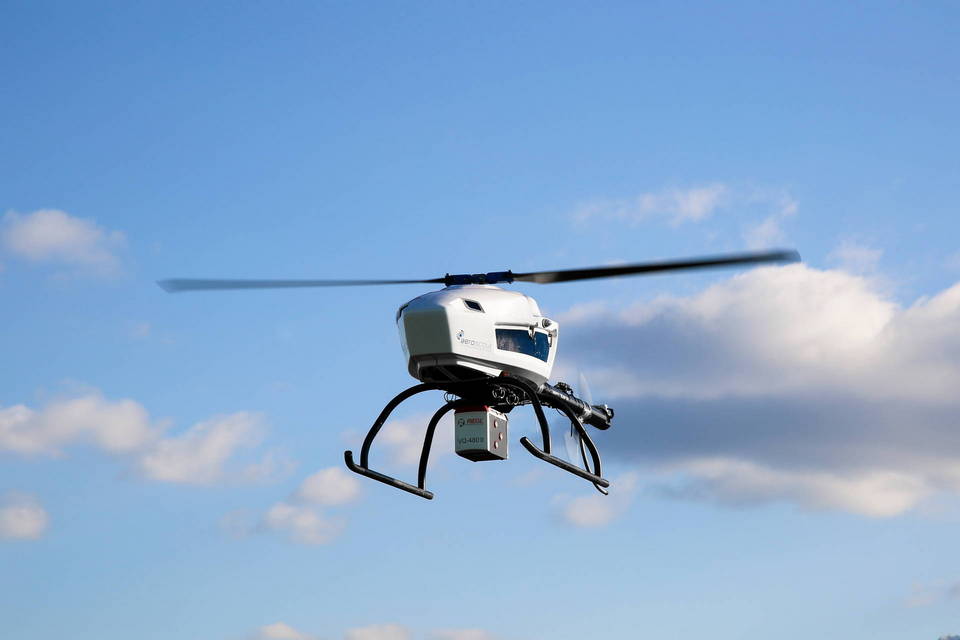
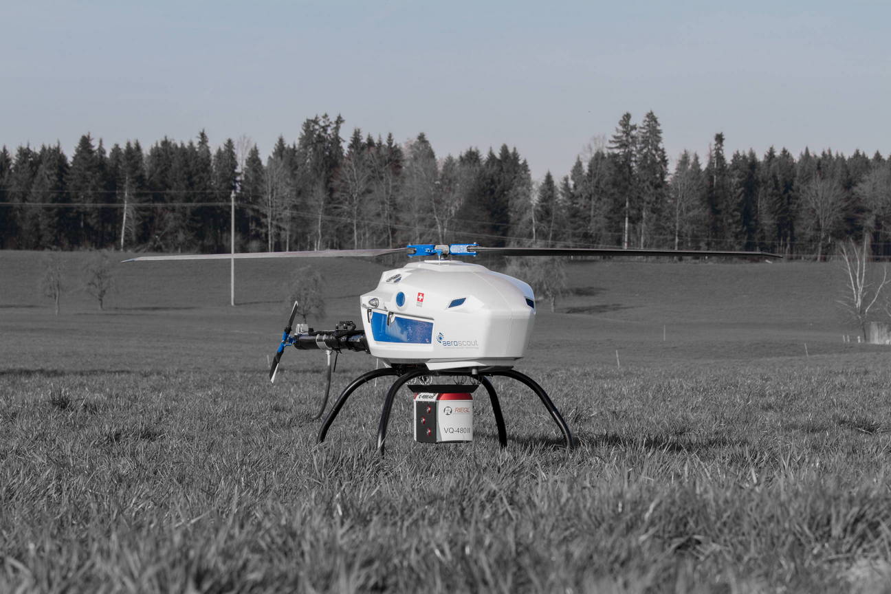
The laser scanner is mounted on the payload bay of the UAV helicopter. The wide scanning angle allows to fly on very low height over ground and scan vertical structures like walls or concrete dams in an optimal way. It is even possible to scan sideways.
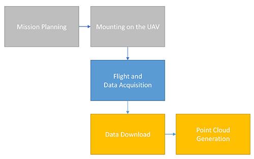
Workflow
1) Missionflightplanning and testing the laser scanner to get the desired point density. This can be done in the laboratory before going out to the flight field.
2) The payload is mounted to the UAV on the flight field within minutes. After the initialization process, (acquiring GPS, establish wireless connection etc.), it is ready for the scan flight.
3) The laser scanner can be started and stopped during the flight. Status information of the scanner and the INS/GPS system is sent continuously to the ground control station and differential GPS correction information is sent to the payload.
4) The laser scan data and the INS/GPS data is recorded and stored onboard. After landing, it can be downloaded to the ground control station laptop.
5) The RIEGL software package (www.riegl.com) is used to process the point cloud by combining laser scan data and INS/GPS position information data.